not a bug, it's actually real transistor behavior 🙏🏽 your LED sits after the last transistor's output (emitter), so when B is on, B's base current flows through the base, out the emitter and straight into your LED, even with A off. that's also your 12 vs 14 mA: emitter current = collector current + base current, so B's ~2 mA joins in. a real breadboard does the same thing. fix: put the LED before the transistors (+ → resistor → LED → transistor → transistor → ground), each input through a resistor into a base. I built both in game: yours lights on 0/1, the fixed one is a perfect AND. for bug reports please use the discord (/bug), it's on the game page and in the download instructions, so I can actually track them: discord.gg/tinylogic
this is fu*king crazy BTW I'm a game dev and learning computer science (i have a basic knowledge about logic gates , cpu architecture but very good at programming) and doing some engineering too so I know how hard this shit is.
This is wild. Going from a single transistor all the way to running DOOM on a CPU you built yourself is such a cool idea. It's clear how much work went into this, especially as a solo dev. Congrats on the early access launch!
thank you, there’s bigger and better things to come especially as a I get more reach and resources to build the game. Thank you again for your comment! :)

← Return to game
Comments
Log in with itch.io to leave a comment.
to people who think this is just a game:
This is seriously impressive and can rival actual professional digital logic simulators and for the price of 10$ its honestly a steal
Do you have any plans to release on Steam?
On the page, it says all early access it buyers get Steam for free planned for mid-late November
I bought it right away.I’ll be cheering you on until the Steam release.You are a Korean who likes games
Bug report: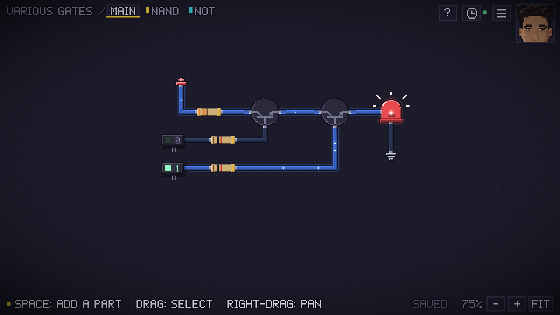 This should be a functional AND gate. Also, the right-hand transistor is outputting 12mA and the LED is reading 14mA in. Weird.
not a bug, it's actually real transistor behavior 🙏🏽 your LED sits after the last transistor's output (emitter), so when B is on, B's base current flows through the base, out the emitter and straight into your LED, even with A off. that's also your 12 vs 14 mA: emitter current = collector current + base current, so B's ~2 mA joins in. a real breadboard does the same thing. fix: put the LED before the transistors (+ → resistor → LED → transistor → transistor → ground), each input through a resistor into a base. I built both in game: yours lights on 0/1, the fixed one is a perfect AND. for bug reports please use the discord (/bug), it's on the game page and in the download instructions, so I can actually track them: discord.gg/tinylogic
Thanks for answering! The fact that some current actually flows between gate and emitter, and that it's enough current to light an LED is kinda funky!
Played the demo, this game is something I'd been hoping to exist for so long. Will be checking out the full game!
the future is here
this person does not sleep
this is fu*king crazy BTW I'm a game dev and learning computer science (i have a basic knowledge about logic gates , cpu architecture but very good at programming) and doing some engineering too so I know how hard this shit is.
This is wild. Going from a single transistor all the way to running DOOM on a CPU you built yourself is such a cool idea. It's clear how much work went into this, especially as a solo dev. Congrats on the early access launch!
thank you, there’s bigger and better things to come especially as a I get more reach and resources to build the game. Thank you again for your comment! :)
That’s an amazing game idea, i’ll definetly check it out
Thank you, I hope once you do that you do enjoy it :)